While browsing through MISUMI USA’s selection of controls product, you may have noticed the many different industrial communication protocols we support. Despite the wide variety of protocols used in automated environments, they can be easily categorized by a simple specification: what physical layer are they operating on?
Today we will explore the history and specifications for some common physical layers and their corresponding communication protocols.
Before we start, it’s worth defining what exactly a physical layer is. The term comes from the Open Systems Interconnection model, which divides any given communication system within a computer network into seven “layers.” The physical layer is the first and lowest layer of the model and encompasses the standards for electrical interfacing. This includes specifications such as voltage levels and line polarity. Keep in mind that this is a separate term from “hardware” (the actual connectors used) and “protocol” (the standards of communication in transmitting/receiving data).
A good way to think of the physical layer is with speech. Imagine you’re in a conversation with someone. Your mouth, tongue, ears and vocal cords would be considered “hardware,” while the way in which you use said body parts to make noises would be the physical layer. The “communication protocol” would thus be the language used to speak to the other person.
RS-232 and RS-485 are the first physical layers that we’ll look at. These two physical layers are referred to as “serial” as they transmit data sequentially through a single channel. In contrast, parallel communication features multiple channels, allowing for larger packets of data to be sent simultaneously.

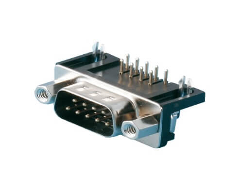
RS-232 is the oldest of the physical layers we will discuss today, first being introduced back in 1960. It was designed as a standard for point-to point data transmission. The layer, along with its corresponding DB-9 and DB-25 connectors, were once a common sight on many computer peripherals; USB and its variants have since become the dominant connector for personal computers. Maximum bandwidth for this physical layer tops out at 1Mb/s (megabit-per-second).
There are several limitations to RS-232 worth mentioning. RS-232 was first standardized with ±25V driver voltages, which meant high power requirements for continuous data transmission. This was improved with later revisions, and modern RS-232 iterations are now driven at ±15V with ±3V logic levels. The maximum operating length (without sacrificing bandwidth) is also limited to a mere 15 meters (50ft) before becoming prone to electromagnetic interference. Due to being designed for point-to-point data transmission, devices in a network need to be daisy-chained together, which may not be possible in more complicated networks.
RS-232 was initially planned to be phased out in favor of RS-422, which offered higher data transmission speeds and less electrical noise, all at greater distances. However, the ubiquity of the DB-type connector combined with its low cost of implementation in a variety of environments has led to the layer’s continued use in the modern era.
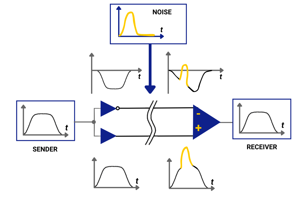
RS-485 is an evolution of the RS-422 physical layer and was first introduced in 1983. It was designed for more complicated topologies but can still be used for basic point-to-point connections. Unlike RS-232, RS-485 incorporates differential signaling, where each channel for transmitting and receiving data has two wires. During data transmission, a voltage signal is sent through each wire. These signals are equal in magnitude but opposite in polarity. The receiving device(s) then compares the two signals and reads the differences in magnitude.
For example, if I were to transmit a 5V signal through differential signaling, it would send a +5V and -5V signal to the receiving device, which would interpret the signals as a single 10V signal. To do the same via RS-232, I would need to send a 10V signal directly to the receiving device. By leveraging this technology, RS-485 can operate on much lower voltage logic levels (±200mV) compared to RS-232 (±3V). This in turn enables faster transmission speeds, as it takes less time for a signal, starting at 0V, to ramp up to +200mV than +3V.
As a result, data bandwidth for RS-485 is significantly higher than RS-232, with a maximum bandwidth of 10Mb/s.
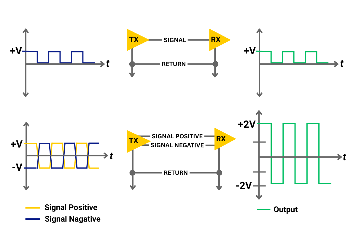
Increased resistance to electromagnetic interference is another benefit of differential signaling. In single-ended signaling systems like RS-232, EMI can obfuscate the difference between the incoming signal and common ground line, making it difficult for the receiver to evaluate the true logic level being sent. EMI can also be picked up on the two wires of a differential signal channel, but it is added equally to both the signals. Because the receiver is only evaluating the difference in voltage between the signals, the EMI is effectively ignored.
Greater EMI resistance allows for a longer operating lengths, with RS-485 being able to transmit data up to 1200 meters (4000ft) before bandwidth is diminished.
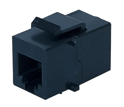
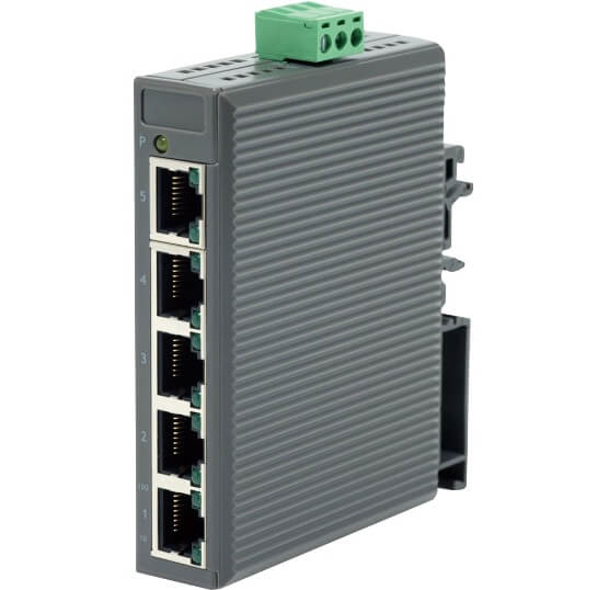
The last physical layer we will discuss before moving onto the communication protocols themselves is one you have probably heard of: Ethernet. First introduced in 1980, the hardware used in Ethernet networks has changed over the years, starting with thick coaxial cables but progressing towards twisted pair and fiber optic cables. For many people, the RJ45 connector head/port has become a universal symbol of networking. The new hardware came with improvements over the previously mentioned physical layers, as Ethernet uses parallel data transmission to achieve higher bandwidths and speeds far faster than RS-232 or RS-485.
While data transfer via RS-485 is capped around 10Mb/s, modern Ethernet networks built on Cat6 or Cat6A can hit 10Gb/s!
While the rate of transmission is greatly improved compared to the serial communication layers, Ethernet compares poorly to RS-485 when it comes to range, being limited (as per Cat6A specifications) to only 100m before bandwidth drops down. This is due to signal decay on the twisted pairs, which increases over longer distances. Ethernet repeaters can mitigate this problem, though it can also be circumvented through choosing an appropriate network topology.
There was a lot of technical information in this section, so please refer to this table for a quick comparison between the 3 physical layers we have discussed.
| RS-232C | RS-485 | Ethernet (Cat6A) | |
|---|---|---|---|
| Transmission Type | Serial | Serial | Parallel |
| Maximum Data Transmission Rate | 1 Mb/s | 10 Mb/s | 10 Gb/s |
| Maximum Cable Length (for Max Transmission Rate) | 15m / 50ft | 1200m / 4000ft | 100m / 330ft |
| Voltage Logic Levels | ±3V | ±200mV | ±2.5V |
| Line Configuration | Point-to-point | Multidrop | Variable |
Now that we understand the differences between some common physical layers, we can discuss some of the protocols that use them.
RS-232 and RS-485 laid the foundation for many of the main communication systems used in industrial environments, such as Modbus RTU (Remote Terminal Unit) and Profibus. The main advantages of these protocols are ease of implementation and cost-effectiveness. Smaller networks may benefit from being able to simply daisy-chain devices together, which alleviates the need for switch boxes.
Another advantage to using serial-based protocols is support for legacy hardware. If you’re using devices that lack support for Ethernet-based hardware, these protocols can work as a substitute. However, Modbus RTU and Profibus suffer from poor scalability with larger and more complicated networks, as adding additional devices may require extensive re-wiring to accommodate them. Being stuck on serial communication also limits the overall bandwidth of data transfer to 10Mb/s.
This is where Ethernet-based protocols come in, such as Profinet, Ethernet/IP and Modbus TCP/IP. While serial-based protocols excel in cost-efficiency and ease of implementation, Ethernet-based protocols are fast and highly scalable. These protocols can support a wider range of network topologies compared to their serial-based counterparts, and adding additional devices beyond the original scope of the network usually requires less effort.
Many “smart” devices within an industrial environment are offering better real-time monitoring and control via IoT, which seamlessly connect to Ethernet protocols. While initial configuration for using these protocols is more complicated and expensive, there may be potential time and monetary savings later down the line when expanding your network.
Hopefully you’ve walked away with a better understanding of the physical layers that shape communication protocols.