
Technical Info
Technical Information including technical terms, how to handle manual stages, and more.
-
Technical information
- Amount of movement
- Stage surface
- Withstand load
- Movement accuracy
- Moment
- Tolerance
-
Selection guide
- Mistake
- Mounting posture
- Parts replacement
-
Installation method/environment
- Installation method
- Scale reading method
- Usage environment
- Maintenance
Technical information
Travel distance (stroke)
The travel distance is the amount of movement of the top table.
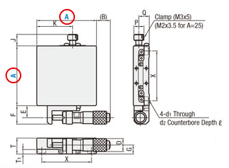
| Part Number | Top View | Front View | Side View | Accessories (4 pcs.) | |||||||||||||||
| Type | A | (B) | Travel Distance (mm) | E | F | J | K | D | G | T | T1 | P | Q | X | d1 | d2 | ℓ | TypeM-L | |
| Micrometer | Feed Screw | ||||||||||||||||||
| X SG XSCG XSBG (40≤A≤100) XSGB (*only) XSCGB (*only) |
25* | 25 | 11 | ±3.2 | 7 | 9 | 6.8 | 15 | 9.3 | 7 | 12 | 3.7 | 6 | 8.5 | 20 | 2.5 | 4.2 | 2.5 | SCB2-4 |
| 40* | 24 | 20.3 | ±6.5 | 12 | 18.5 | 11.5 | 26 | 13 | 9 | 16 | 4.5 | 10 | 10.5 | 32 | 3.5 | 6 | 3.5 | SCB3-6 | |
| 50 | 19 | 15.3 | 12 | 18.5 | 11.5 | 31 | 13 | 9 | 16 | 4.5 | 10 | 10.5 | 40 | 3.5 | 6 | 3.5 | SCB3-6 | ||
| 60* | 14 | 10.3 | 12 | 18.5 | 11.5 | 36 | 13 | 9 | 16 | 5 | 10 | 10.5 | 50 | 4.5 | 8 | 4 | SCB4-6 | ||
| 70 | 14.5 | 10.8 | 12 | 18.5 | 11.5 | 46.5 | 13 | 10 | 18 | 6 | 10 | 11.5 | 60 | 4.5 | 8 | 4.5 | SCB4-6 | ||
| 80* | 43.5 | 10 | ±12.5(*1) | 17 | 22(*3) | 11.5 | 55 | 18 | 11 | 20 | 6.5 | 10 | 14.5 | 70 | 4.5 | 8 | 5.3 | SCB4-6 | |
| 100 | 28.5 | -5(*2) | 17 | 22(*3) | 11.5 | 67.5 | 18 | 11 | 20 | 6.5 | 10 | 14.5 | 90 | 4.5 | 8 | 5.3 | SCB4-6 | ||
* About the "±" notation of the travel distance
- Dimensional drawings are shown at the stroke center.
- Dimensions described in () are dimensions that change according to the stroke movement.
- A model marked with * indicates a different amount of movement based on feed mechanism.
- Example of Travel Distance noted with "±"symbol: The "±" symbol indicates travel disctance in both directions from the center. For example, ±6.5mm is a full stroke of 13mm.
- If Travel Distance is not noted with ± then the value is as stated. For example, 20mm is a stroke of 20mm.
-
[For XWG60]
-
[For ZLFG40]
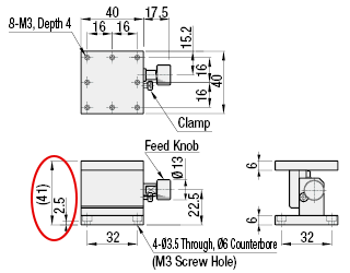
The stroke is ± 5mm (10mm).
The stage height dimension (41) means that it varies from 36mm (-5mm) to 46mm (+ 5mm).
Stage surface
The size of the stage surface on which the work is placed.
| Part Number | A | Stage Surface (mm) | Load Capacity (N) | Travel Accuracy | Moment Load Capacity (N·m) | Moment Rigidity ("/N·cm) | Parallelism | Weight (kg) | |||||||||
| Type | Horizontal | Vertical | Straightness | Motion Parallelism | Pitching | Yawing | Pitching | Yawing | Rolling | Pitching | Yawing | Rolling | Micrometer | Feed Screw | |||
| XSG XSCG XSBG (40≤A≤100) XSGB (*only) XSCGB (*only) |
25* | 25x25 | 39.2 | 9.8 | 3µm | 10µm | 30" | 25" | 2.0 | 2.0 | 3.5 | 1.9 | 1.1 | 1.1 | 30µm | 0.07 | 0.09 |
| 40* | 40x40 | 98 | 49 | 1µm (*4) |
7µm | 25" | 15" | 5.0 | 5.0 | 5.0 | 0.42 | 0.35 | 0.21 | 15µm | 0.23 | 0.23 | |
| 50 | 50x50 | 147 | 6.8 | 6.8 | 6.0 | 0.15 | 0.14 | 0.09 | 0.28 | 0.28 | |||||||
| 60* | 60x60 | 196 | 10.0 | 10.0 | 9.0 | 0.08 | 0.08 | 0.05 | 0.40 | 0.40 | |||||||
| 70 | 70x70 | 225.4 | 13.8 | 13.8 | 12.9 | 0.06 | 0.05 | 0.03 | 0.58 | 0.58 | |||||||
| 80* | 80x80 | 264.6 | 3µm | 8µm | 18.2 | 18.2 | 17.7 | 0.04 | 0.04 | 0.02 | 20µm | 0.90 | 0.84 | ||||
| 100 | 100x100 | 343 | 31.8 | 31.8 | 30.7 | 0.02 | 0.02 | 0.01 | 1.33 | 1.27 | |||||||
・ The stage surface is AxA.
・ If A = 25, it is 25mmx25mm.
-There is a mounting hole on the stage surface.
-The mounting holes provided differ depending on the product.
・ Information on hole size is also posted in the catalog.
Withstand load
| Part Number | Stage Surface (mm) | Load Capacity (N) | Travel Accuracy | Moment Load Capacity (N·m) | Moment Rigidity ("/N·cm) | Parallelism | Weight (kg) | ||||||||||
| Type | A | Horizontal | Vertical | Straightness | Motion Parallelism | Pitching | Yawing | Pitching | Yawing | Rolling | Pitching | Yawing | Rolling | Micrometer | Feed Screw | ||
| XSG XSCG XSBG (40≤A≤100) XSGB (*only) XSCGB (*only) |
25* | 25x25 | 39.2 | 9.8 | 3µm | 10µm | 30" | 25" | 2.0 | 2.0 | 3.5 | 1.9 | 1.1 | 1.1 | 30µm | 0.07 | 0.09 |
| 40* | 40x40 | 98 | 49 | 1µm (*4) |
7µm | 25" | 15" | 5.0 | 5.0 | 5.0 | 0.42 | 0.35 | 0.21 | 15µm | 0.23 | 0.23 | |
| 50 | 50x50 | 147 | 6.8 | 6.8 | 6.0 | 0.15 | 0.14 | 0.09 | 0.28 | 0.28 | |||||||
| 60* | 60x60 | 196 | 10.0 | 10.0 | 9.0 | 0.08 | 0.08 | 0.05 | 0.40 | 0.40 | |||||||
| 70 | 70x70 | 225.4 | 13.8 | 13.8 | 12.9 | 0.06 | 0.05 | 0.03 | 0.58 | 0.58 | |||||||
| 80* | 80x80 | 264.6 | 3µm | 8µm | 18.2 | 18.2 | 17.7 | 0.04 | 0.04 | 0.02 | 20µm | 0.90 | 0.84 | ||||
| 100 | 100x100 | 343 | 31.8 | 31.8 | 30.7 | 0.02 | 0.02 | 0.01 | 1.33 | 1.27 | |||||||
XSG / XSGB: Micrometer head minimum reading 10µm / scale (* 5) The straightness of XSGB and XSCGB40 / 60 is 3µm.
* 4 In the MISUMI Catalog, the static load capacity is also shown in parentheses as a reference value. See page 1953 for details.
1. What is load capacity?
The Load Capacity is the amount of force the stage can withstand when the load is placed in the center of the stage surface.
If the product is used beyond the load capacity, the stage may not operate smoothly.
Please refer to the value of "horizontal" for the load capacity when installed horizontally and the value of "vertical" for the load capacity when installed vertically.
If there is no "horizontal" or "vertical" in the standard table, <FAQ: Can I use it upside down or sideways? Please check.
Please note that installing the stage upside down or in vertical orientation may affect the accuracy.
* Unit of load capacity: N (Newton) → Approximately 0.102 kgf (kilogram-force) in terms of kgf.
2. What is static load capacity?
The Static Load Capacity is the amount of force the stage can withstand while stationary when the load is placed in the center of the stage surface.
For some products, in addition to the normal load capacity, the static load capacity is also shown in parentheses.
In the representative sample, after applying the load in (), the load is removed and it is confirmed that the accuracy does not change before and after the test.
Static load capacity is usually not stated for dovetail groove type stages because the dovetail structure is very strong in when stationary.
Movement accuracy
The movement accuracy described on the multi-axis stage such as the XY axis is the value when measured with a single axis.
| Part Number | Stage Surface (mm) | Load Capacity (N) | Travel Accuracy | Moment Load Capacity (N·m) | Moment Rigidity ("/N·cm) | Parallelism | Weight (kg) | ||||||||||
| Type | A | Horizontal | Vertical | Straightness | Motion Parallelism | Pitching | Yawing | Pitching | Yawing | Rolling | Pitching | Yawing | Rolling | Micrometer | Feed Screw | ||
| XSG XSCG XSBG (40≤A≤100) XSGB (*only) XSCGB (*only) |
25* | 25x25 | 39.2 | 9.8 | 3µm | 10µm | 30" | 25" | 2.0 | 2.0 | 3.5 | 1.9 | 1.1 | 1.1 | 30µm | 0.07 | 0.09 |
| 40* | 40x40 | 98 | 49 | 1µm (*4) |
7µm | 25" | 15" | 5.0 | 5.0 | 5.0 | 0.42 | 0.35 | 0.21 | 15µm | 0.23 | 0.23 | |
| 50 | 50x50 | 147 | 6.8 | 6.8 | 6.0 | 0.15 | 0.14 | 0.09 | 0.28 | 0.28 | |||||||
| 60* | 60x60 | 196 | 10.0 | 10.0 | 9.0 | 0.08 | 0.08 | 0.05 | 0.40 | 0.40 | |||||||
| 70 | 70x70 | 225.4 | 13.8 | 13.8 | 12.9 | 0.06 | 0.05 | 0.03 | 0.58 | 0.58 | |||||||
| 80* | 80x80 | 264.6 | 3µm | 8µm | 18.2 | 18.2 | 17.7 | 0.04 | 0.04 | 0.02 | 20µm | 0.90 | 0.84 | ||||
| 100 | 100x100 | 343 | 31.8 | 31.8 | 30.7 | 0.02 | 0.02 | 0.01 | 1.33 | 1.27 | |||||||
1. Straightness (unit: μm)
The maximum displacement in horizontal and vertical planes from an ideal straight line measured during a full stroke movement.
<Measurement method> (Fig. A-1)
- Displacement is meansured at predetermined intervals while moving from one end of the stroke limit to the other.
- The maximum difference between measured values as they deviate from an ideal straight line is the "straightness" (ideal movement axis) (Fig. B).
(A) Fixed position of dial gauge

Figure: (A-1) Straightness
2. Parallelism of motion (unit: μm)
Also called "Motion Parallelism". The displacement of a stage in the horizontal plane measured during a full stroke movement.
<Measurement method>(Fig. A-2)
- A dial gauge is fixed to the stage surface, the gauge tip is placed onto the base plate. (Fig. A-2)
- Displacement is measured at predetermined intervals from one end of the stroke limit to the other.
- The maximum difference between the mesured values is the "Motion Parallelism". (Fig. B).
* The difference between straightness and verticality of motion for horizontal Z-axis stage.
◆ Straightness (Unit: μm)
- Maximum deviation in both horizontal and vertical directions with respect to the ideal movement axis.
◆ Verticality of movement (unit: μm)
- The horizontal Z-axis stage and a right angle reference is fixed on the base plate.
- Displacement is measured between the right angle reference and the measureing device set on the stage surface.
- The displacement measured at the end point is the Verticality of Motion.

Figure: (A-2) Parallelism of motion *same as Fig. A-1
(Reference) Parallelism at rest (unit: μm)
Parallelism between the stage surface and reference plant measured with the stage at rest. (positions shown in drawing). (Fig. A-3)
* For details, see "Geometric tolerance: Parallelism".
"Parallelity" is a value measured when the stage is in the reference position.
Unlike "parallelism of motion", it is not an indicator of movement accuracy.

Figure: (A-3) Resting parallelism
3. Pitching yawing (unit: "[arcsecond])
A measure of how much the stage surface "twists" during linear motion compared to a reference point.
* 1 "[arcsecond] = 1/60'[arcminute] = 1 / 3,600 ° [degree] ≒ 0.00028 °
<Measurement method>
- Angle of displacement is measured at regular intervals through full stroke of the stage.
- The angle of displacement in the vertical plane parallel to the direction of motion is the "pitch" and the maximum value in the horizontal plane is the "yaw".
Differences in pitching, yawing and rolling (Fig. C)
With respect to the direction of travel
- Pitch: Rotation on the plane parallel with direction of movement (tilts up and down).
- Yaw: Rotation in the horizontal plane (spins, or "fishtails").
- Roll: Rotation on the plane perpendicular to the direction of movement (tilt left and right).
* Roll often cannot be measured during motion and is left out of Accuracy Standards specifications.

Figure: (B) Difference between straightness and parallelism of motion

Figure: (C) Expression of inclination
4.XY orthogonality (unit: μm)
The degree of orthogonality of the Y movement axis with respect to the X movement axis.
5. Eccentricity of Rotation (unit: μm)
Also called Radial runout. The amount of horizontal displacement from the center of rotation of the stage surface during motion.
6. Surface runout of rotating stage (unit: μm)
Also called Axial runout. The amount of vertical displacement measured from the outer edge of the stage surface during motion.
Allowable moment load / moment rigidity
| Part Number | Stage Surface (mm) | Load Capacity (N) | Travel Accuracy | Moment Load Capacity (N·m) | Moment Rigidity ("/N·cm) | Parallelism | Weight (kg) | ||||||||||
| Type | A | Horizontal | Vertical | Straightness | Motion Parallelism | Pitching | Yawing | Pitching | Yawing | Rolling | Pitching | Yawing | Rolling | Micrometer | Feed Screw | ||
| XSG XSCG XSBG (40≤A≤100) XSGB (*only) XSCGB (*only) |
25* | 25x25 | 39.2 | 9.8 | 3µm | 10µm | 30" | 25" | 2.0 | 2.0 | 3.5 | 1.9 | 1.1 | 1.1 | 30µm | 0.07 | 0.09 |
| 40* | 40x40 | 98 | 49 | 1µm (*4) |
7µm | 25" | 15" | 5.0 | 5.0 | 5.0 | 0.42 | 0.35 | 0.21 | 15µm | 0.23 | 0.23 | |
| 50 | 50x50 | 147 | 6.8 | 6.8 | 6.0 | 0.15 | 0.14 | 0.09 | 0.28 | 0.28 | |||||||
| 60* | 60x60 | 196 | 10.0 | 10.0 | 9.0 | 0.08 | 0.08 | 0.05 | 0.40 | 0.40 | |||||||
| 70 | 70x70 | 225.4 | 13.8 | 13.8 | 12.9 | 0.06 | 0.05 | 0.03 | 0.58 | 0.58 | |||||||
| 80* | 80x80 | 264.6 | 3µm | 8µm | 18.2 | 18.2 | 17.7 | 0.04 | 0.04 | 0.02 | 20µm | 0.90 | 0.84 | ||||
| 100 | 100x100 | 343 | 31.8 | 31.8 | 30.7 | 0.02 | 0.02 | 0.01 | 1.33 | 1.27 | |||||||
1. Moment Load Capacity (unit: N ・ m)
The force that the stage can withstand when the load is off center from the stage surface. If the center of gravity of the workpiece is located away from the center of the stage surface, check the Moment Load Capacity as well as the Load Capacity.
Products with high capacity are "high rigidity".
2. Moment rigidity (Unit: "[arcsec] / N ・ cm)
It is the angle (″ [arcsec]) at which the stage surface tilts when a unit moment load (1N ・ cm) is applied.
Moment rigidity is defined in three directions (pitch, yaw, roll).
Tolerance
1. Dimensional tolerance
Dimensional Tolerances that are not listed in the catalog should be assumed to be intermediate tolerances.
For normal tolerances, refer to JIS B 0405: 1991.
2. Geometric tolerance: Parallelism (unit: μm)
| Part Number | Stage Surface (mm) | Load Capacity (N) | Travel Accuracy | Moment Load Capacity (N·m) | Moment Rigidity ("/N·cm) | Parallelism | Weight (kg) | ||||||||||
| Type | A | Horizontal | Vertical | Straightness | Motion Parallelism | Pitching | Yawing | Pitching | Yawing | Rolling | Pitching | Yawing | Rolling | Micrometer | Feed Screw | ||
| XSG XSCG XSBG (40≤A≤100) XSGB (*only) XSCGB (*only) |
25* | 25x25 | 39.2 | 9.8 | 3µm | 10µm | 30" | 25" | 2.0 | 2.0 | 3.5 | 1.9 | 1.1 | 1.1 | 30µm | 0.07 | 0.09 |
| 40* | 40x40 | 98 | 49 | 1µm (*4) |
7µm | 25" | 15" | 5.0 | 5.0 | 5.0 | 0.42 | 0.35 | 0.21 | 15µm | 0.23 | 0.23 | |
| 50 | 50x50 | 147 | 6.8 | 6.8 | 6.0 | 0.15 | 0.14 | 0.09 | 0.28 | 0.28 | |||||||
| 60* | 60x60 | 196 | 10.0 | 10.0 | 9.0 | 0.08 | 0.08 | 0.05 | 0.40 | 0.40 | |||||||
| 70 | 70x70 | 225.4 | 13.8 | 13.8 | 12.9 | 0.06 | 0.05 | 0.03 | 0.58 | 0.58 | |||||||
| 80* | 80x80 | 264.6 | 3µm | 8µm | 18.2 | 18.2 | 17.7 | 0.04 | 0.04 | 0.02 | 20µm | 0.90 | 0.84 | ||||
| 100 | 100x100 | 343 | 31.8 | 31.8 | 30.7 | 0.02 | 0.02 | 0.01 | 1.33 | 1.27 | |||||||
Comparison of flatness measurement between the stage surface and fixed reference plane. Any tilt that is measured is recorded as "parallelism".
"Parallelity" is a value measured when the stage is in the reference position. Unlike "parallelism of motion", it is not an indicator of movement accuracy.
<Measurement method>
- Place the dial gauge fixed to the surface plate on the upper surface of the stage (see the figure on the right).
- Slide the stage on the surface plate while keeping the reference position, and measure the displacement of the entire stage.
- The maximum difference between the measured values is "(stationary) parallelism".
Some models cannot be reconfigured due to their structure. Please look for "Alterations" notes in each Drawings/Specifications tab for detials.
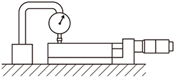
Figure: Dial gauge fixed position when measuring parallelism
Selection guide
Mistake (mounting position of feed mechanism)
For many high precision manual stages, designation "C" (see figure below) is the standard "normal position". Other configurations can be selected depending on the mounting space, mounting posture, and operating conditions.
Some models cannot be reconfigured due to their structure. Please look for "Alterations" notes in each Drawings/Specifications tab for detials.
- ・ Center / side push
Both Micrometer head and feed screw types have center push and side push options. - ・ Left-right difference
A mirror image of feed and clamp configuration can be selected if such configuration is a better fit for a devices design.
Example: A and AR in the table. - ・ Upside down
This feed method is handy when mounting the stage in vertical orientation. The load needs to be received by the tip of the micromter. For details, see "Selection Guide: Mounting Posture".
| Side push | Center push | ||
|---|---|---|---|
|
(C) Normal position (basic mounting position)  |
(CR) Left-right difference  |
(A) Center  |
(AR) Left and right center difference  |
|
(CZ) Up and down difference  |
(CZR) Left / right / up / down difference  |
(AZ) Center top and bottom difference  |
(AZR) Center left, right, up and down  |
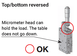
Mounting posture
X-axis stage
The stage using the cross roller guide and the linear ball guide has a spring inside to utilize the reaction force of the return.
When mounting an X-axis stage in a vertical orientation, the feed mechanism needs to support the load to ensure proper operation (see the figure below).
* The position of the feed mechanism can be selected in "Additional machining".
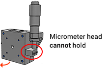
| NG | OK |
| If a load greater than the force pulled by the spring is applied, the load will not be received and the stage surface will slide down. | CZ, CZR: The load applied to the stage surface can be received by the micrometer head and the bracket attached to the bottom plate, so the upper surface of the stage does not drop. For normal CR, A, AR: The micrometer tip should face down to prevent the stage from lowering. CZ, AZ, CZR, and AZR are designed to have the tip facing up. |
 |
 |
Vertical difference (Z type)
These types are designed to have the micrometer head facing up. The bracket design ensures that the feed mechanism will recieve the load.

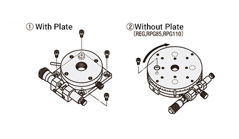
Rotating stage and goniometer stage
When using it to generate a moment load in the direction of rotation, it can be used only in the direction in which the load is received on the micrometer head side.
Please note that it cannot be used if the load is not received on the micrometer head side.
Also, if it is mounted on the side, the load capacity will decrease. See also FAQ: Can I use it upside down or sideways?
| NG | OK |
 |
 |
Parts replacement
Replacement of micrometer head
We do not recommend that you replace the micrometer head yourself.
If you do not need a micrometer head, please consider a product that allows you to select no micrometer head by alterations.
Please note that if you replace the micrometer head yourself, the product will not be covered by the warranty.
* Target products: XSG , XPG , FSXR , FSXYR , FSZR
Replacing the feed screw and the handle of the rack and pinion
Replacing the lead screw or the handle of the rack and pinion is not recommended as it requires disassembly that may affect accuracy and mechanism.
You can use a "handle cover" to increase the handle diameter or "handle extension" to extend the handle without changing it out.
* Target products: Handle cover HDCVR , extension cover HDEXT
Replacing the clamp knob
We do not recommend replacing the clamp knob.
Please note that if you replace the clamp knob yourself, the product will not be covered by the warranty.
* For details , please see the MISUMI Terms and Conditions.
Usage guide
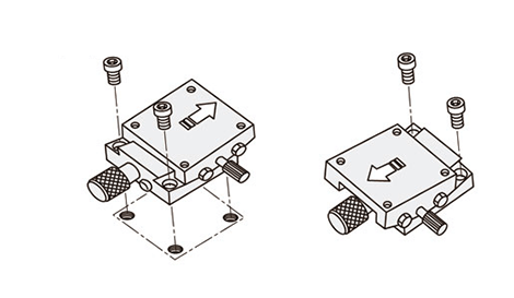
Installation method
When mounting the stage on the base, basically move the stage surface to mount it. Please refer to the following illustration.
1. Linear stage

2. Rotating stage
3. Goniometer stage
Precautions for installation
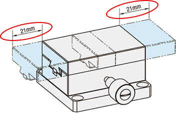
1. Flatness of the mounting surface
If the flatness of the fixed surface of the stage or the parts attached to the stage surface is insufficient, the original performance of the product may not be exhibited.
The recommended flatness is within 0.01 mm.
| Precautions on the installation surface for mounting the stage | Precautions for parts to be attached to the stage |
|---|---|
 |
 |
| The stage distorts into a U shape causing the guide (red circle in the figure above) to release preload causing more play. If distorted in the other direction, the guide may become "over preloaded" affecting accuracy and durability. | The stage distorts into a U shape causing the guide (red circle in the figure above) to release preload causing more play. If distorted in the other direction, the guide may become "over preloaded" affecting accuracy and durability. |
2. Screw length
When fixing parts to the stage, select bolts that are less than or equal to the tap depth on the top surface of the stage.
If bolts that are too long are used, they may interfere with internal parts and cause deterioration of product slidability or malfunction.
How to read the scale
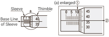
1. Micrometer head
<How to read>
- (1) Read how many mm the thimble end face is on the sleeve in 0.5 mm increments.
(11.5 mm in the case of the right figure) - (2) Read the thimble value at the position where the sleeve baseline and thimble scale line match.
(0.36 mm in the case of the right figure) - ③ The sum of 1 and 2 is the reading. (11.86 mm in the case of the right figure)
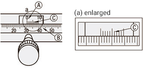
2. Vernier scale
<How to read>
- ① Read the 0 position of the vernier scale Ⓐ in 1 mm increments on the scale of the main scale Ⓑ.
(30 mm in the case of the right figure) - (2) Of the scales in Ⓐ, read the scale Ⓒ that matches the scale in Ⓑ, and use that as the numerical value in units of 0.1 mm.
(0.6 mm in the case of the right figure) - ③ The sum of 1 and 2 is the reading. (30.6 mm in the case of the right figure)
Usage environment
About the usage environment of the manual stage and the characteristics of the product
・ Operating environment: 10 to 50 ° C, humidity 20 to 70% RH (non-condensing)
・ Recommended operating environment: 22 ± 5 ° C, humidity 20 to 70% RH (non-condensing)
* Avoid using in the following places.
- ・ Places with a lot of dust and dust (especially metal powder)
- ・ Places exposed to direct sunlight or radiant heat
- ・ Near fire
- ・ Where gas and flammable gas are generated
- ・ Where it gets wet or oily
- ・ Where vibration and impact are transmitted
- ・ Places with a lot of salt and organic solvents
About use in vacuum
Our products are not tested in a vacuum chamber.
Some stage models (*) can be configured to use vacuum chamber grease. Contact us for more details.
Please note that vacuum compatibility is not certified, only the grease is certified for vacuum chamber use.
* Target products: Linear ball stages ( XSG , FSXR , FSXYR , FSZR )
About use in a clean environment
Only specific stages would support cleanroom environments. Some have cleanroom grease as standard, others can be configured with cleanroom grease.
JIS class 6 (US federal standard class 1000) cleanroom environment grease is used. Please use this at your own discretion.
"R (For Clean Environment)" can be selected to configure on certain models.
* Target products: Linear ball stages ( XSG , FSXR , FSXYR , FSZR )
About use in water or in places where it may be exposed to water
Unfortunately, there is no stage that can be used underwater or in places where it may be exposed to water.
This is because the stage is made up of multiple parts, which can rust due to water and also affect the grease.
About magnetism
Our stainless steel stages will be affected by magnetic forces on the base and surface. If magnetic forces are a concern, we recommend using aluminum body stages.
Please note that aluminum stages may still contain parts that are affected by magnetic forces (screws, nuts, etc...).
About dustproof
We do not handle dustproof stages.
About maintenance
About grease
The model number of grease varies depending on the type of stage, so please contact us individually.
Grease-up frequency
Regardless of the type of grease, there are no regular standards.
It depends on the driving conditions and the type of guide, but check the grease condition about once a month and apply it if necessary.
Grease-up method
Follow the procedure below.
- Wipe off the old grease as far as you can see.
- Apply to the guide using a syringe or the like.
- Perform the full stroke operation several times.
- Wipe off the excess grease.
Grease removal
Grease removal: Grease removal is not recommended because the purpose of applying grease is to ensure smooth operation of the product and prevent wear and misalignment.
Please note that if it is removed, the product will not be covered by the warranty.