You’re almost finished brainstorming an awesome design when you realize a critical moving part will come to an abrupt stop and experience shock. This can lead to a handful of issues such as unnecessary wear, damaged products, and even downed machinery.
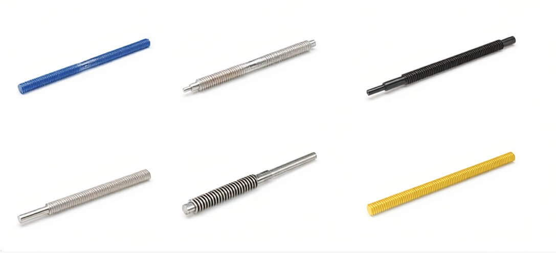
One way to prevent these issues is by using shock absorbers.
This guide will help you find the best shock absorber for your linear application. As we dive in, I’ll describe a linear application as a load moving in a straight line with the potential for shock.
Initial Parameters
The first thing required when sizing a shock absorber is understanding the properties of your system. This can be separated into four main parts:
- Mass (M) in kg
- Velocity (V) in m/s
- Propelling Force (F) in N
- Cycles per hour (c)
Rotary applications will require more parameters but aren’t covered in this practice. For this example, let’s say M = 90 kg, V = 2.05 m/s, c = 300/hr, and let’s put F on hold for now.
Kinetic Energy and Work Energy
With the information above, we’ll be using the following formula to determine kinetic energy (Ek) in Nm for a horizontal moving load:
Ek = ½ M V2
Ek = ½ (90) (2.05)2
Ek = 190 Nm
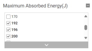
Now let’s take a look at MISUMI’s Shock Absorbers page, specifically under the “Maximum Absorbed Energy (J)” filter on the left side of the page. Here, you want to select an energy that is equal to or more than the number we just found, 190 Nm.
Depending on the shock absorber selected, we’ll need to get the stroke (S) in m to determine work energy (Ew). Choosing the ENIDINE option, MAWC1251W, we find a stroke of S = 0.025 m.

To pick back up on what the F is, we have a few different scenarios. If your load is moving horizontally without any propelling force, F = 0 N and you’ll only have to worry about kinetic energy.

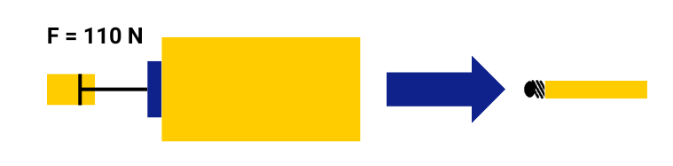
If you have a propelling force, possibly from an air cylinder or a motor which will be application specific, you will use that number in the formula below for work energy. We will use F = 110 N:
Ew = F S
Ew = (110) (0.025)
Ew = 2.75 Nm
Things are a bit different if your load is moving vertically in freefall. The equation for kinetic energy (Ek) will be calculated as follows with g being 9.81 m/s2 and h being the height that the load is released measured in m. We will use a height of h = 0.5 m:
Ek = g M h
Ek = (9.81) (90) (0.5)
Ek = 440 Nm
You’ll notice the energy is more than twice the amount of our horizontal example, which would require a new selected shock absorber.

Total Energy per Cycle and Total Energy per Hour
Now that we have our Ek = 190 Nm and Ew = 2.75 Nm, we can add them together to get the total energy per cycle (Ec):
Ec = Ek + Ew
Ec = 190 + 2.75
Ec = 193 Nm/c
In one last step, we can find the total energy per hour (Et) using the following formula:
Et = Ec c
Et = (193) (300)
Et = 5790 Nm/hr
And when we compare this to the Etmax of the selected shock at 111400 Nm/hr while considering ENIDINE’s suggestion of a minimum of 5% maximum rated energy per cycle, we find we are within the suggested range with significant room for potentially increased loads.
Now you have another tool to add to your belt in selecting shock absorbers. If you’re experiencing a more unique setup, feel free to reach out to MISUMI’s engineering team for product help.
With brands like ACE Controls, ENIDINE, and SMC, we’re sure to find something that can fit your application.